
- Joined
- Nov 2, 2017
- Messages
- 8,982
- Likes
- 1,141
- Points
- 4,577
- Age
- 41
- Location
- Tbilisi
- Website
- alexlaptoprepair.com
LPCAMM2 SAY Goodbye to the Laptop RAM circuit
and here the list of the important voltages and signals to check LPDDR5 CAMM2 faults for modern laptops.

In recent days, Lenovo has released the world's first laptop featuring LPDDR5 CAMM2 memory, a module developed by SAMSUNG. This new module is an improvement over DELL's CAMM and is expected to become widespread in the coming years for several reasons. One of the primary benefits is that it addresses the recurring failures seen in embedded RAM chips on laptop motherboards and the issues with Apple’s Unified Memory in their devices over the past few years. They had to solder RAM chips alongside processors to achieve the required speed, but this led to numerous failures. With limited spare parts, many laptops became died and unusable, and several models gained a poor reputation.
The new module offers multiple times the data transfer speed while consuming 60% less power compared to previous technologies. This means more efficient and faster performance, fewer battery charges, longer lifespan, and lower temperatures. The design also allows users to replace the module themselves, with the connector being easily replaceable, eliminating the issues associated with built-in RAM failures. Currently, the module is available in capacities ranging from 16GB to 128GB.
For specialists
The module has 644 pins, and the PCB consists of 10 to 16 layers, making its size approximately 8cm × 3cm. Another significant advantage is that there is no longer a RAM circuit on the laptop motherboard in models that support this module. The module takes 5V from the power system and converts it to several voltages, which I will list at the end of this post, along with important signals that will help us troubleshoot issues in future generations using schematics . This means repair will be easier. For example, the recently released model uses the PMIC5200 chip, which provides all the necessary voltages, whether PWM or LDO, for the module and the processor. The old SPD system couldn't be used because the module functions as more than just RAM in a single piece, so they relied on the SPD5118, an SPD HUB IC.
The recently released laptop model is the ThinkPad P1 Gen 7.
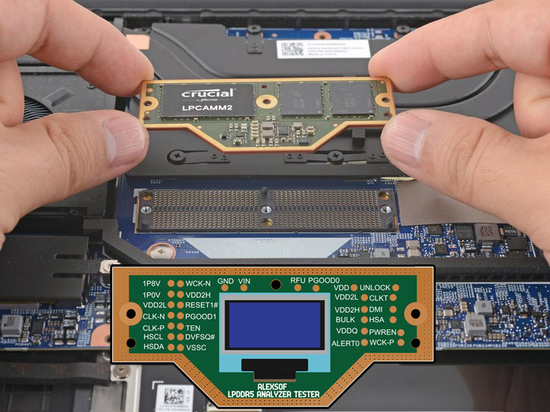
Fortunately, in recent days, the initial design for ALEXSOF LPCAMM2 ANALYZER TESTER . This tester will be installed in the module's connector to measure important signals and pins, and display POST CODES, which will aid us in troubleshooting faults. I plan to start testing as soon as the module becomes widely available in the market. Below is a list of the main voltages and some signal names related to the module that will be tracked without a tester using the laptop’s schematic.
- 1.1V, 0.5V, 1.05V
- VDD2L=0.9V
- VDD2H=1.05V
- VDDQ=0.5V
- VDD=1.1V
- HSCL=1.0V
- HSDA=1.0V
- HSA=2.1V
- VPP=1.8V
- DVFSQ#=1.8V
- PWR_EN=1.8V
- UNLOCK=1.8V
- DQS=VDDQ
- DQ0=VDDQ
- DMI=VDDQ
- WCKT,C=VDDQ
- RESET#=80-20% of VDDQ
- CLK_T=VDD
- CLK_C=VDD
- CLK-N=F-EDGE
- CLK-P=R-EDGE
- VIN_BULK=5V
- REG= 46, 4A, 4C
- TSD=1024 byte
and here the list of the important voltages and signals to check LPDDR5 CAMM2 faults for modern laptops.
In recent days, Lenovo has released the world's first laptop featuring LPDDR5 CAMM2 memory, a module developed by SAMSUNG. This new module is an improvement over DELL's CAMM and is expected to become widespread in the coming years for several reasons. One of the primary benefits is that it addresses the recurring failures seen in embedded RAM chips on laptop motherboards and the issues with Apple’s Unified Memory in their devices over the past few years. They had to solder RAM chips alongside processors to achieve the required speed, but this led to numerous failures. With limited spare parts, many laptops became died and unusable, and several models gained a poor reputation.
The new module offers multiple times the data transfer speed while consuming 60% less power compared to previous technologies. This means more efficient and faster performance, fewer battery charges, longer lifespan, and lower temperatures. The design also allows users to replace the module themselves, with the connector being easily replaceable, eliminating the issues associated with built-in RAM failures. Currently, the module is available in capacities ranging from 16GB to 128GB.
For specialists
The module has 644 pins, and the PCB consists of 10 to 16 layers, making its size approximately 8cm × 3cm. Another significant advantage is that there is no longer a RAM circuit on the laptop motherboard in models that support this module. The module takes 5V from the power system and converts it to several voltages, which I will list at the end of this post, along with important signals that will help us troubleshoot issues in future generations using schematics . This means repair will be easier. For example, the recently released model uses the PMIC5200 chip, which provides all the necessary voltages, whether PWM or LDO, for the module and the processor. The old SPD system couldn't be used because the module functions as more than just RAM in a single piece, so they relied on the SPD5118, an SPD HUB IC.
The recently released laptop model is the ThinkPad P1 Gen 7.
Fortunately, in recent days, the initial design for ALEXSOF LPCAMM2 ANALYZER TESTER . This tester will be installed in the module's connector to measure important signals and pins, and display POST CODES, which will aid us in troubleshooting faults. I plan to start testing as soon as the module becomes widely available in the market. Below is a list of the main voltages and some signal names related to the module that will be tracked without a tester using the laptop’s schematic.
- 1.1V, 0.5V, 1.05V
- VDD2L=0.9V
- VDD2H=1.05V
- VDDQ=0.5V
- VDD=1.1V
- HSCL=1.0V
- HSDA=1.0V
- HSA=2.1V
- VPP=1.8V
- DVFSQ#=1.8V
- PWR_EN=1.8V
- UNLOCK=1.8V
- DQS=VDDQ
- DQ0=VDDQ
- DMI=VDDQ
- WCKT,C=VDDQ
- RESET#=80-20% of VDDQ
- CLK_T=VDD
- CLK_C=VDD
- CLK-N=F-EDGE
- CLK-P=R-EDGE
- VIN_BULK=5V
- REG= 46, 4A, 4C
- TSD=1024 byte
Last edited:


